Uml Class Diagram Notation Pdf
What is Class in UML Diagram?
A Class in UML diagram is a blueprint used to create an object or set of objects. The Class defines what an object can do. It is a template to create various objects and implement their behavior in the system. A Class in UML is represented by a rectangle that includes rows with class names, attributes, and operations.
What is Class Diagram?
A Class Diagram in Software engineering is a static structure that gives an overview of a software system by displaying classes, attributes, operations, and their relationships between each other. This Diagram includes the class name, attributes, and operation in separate designated compartments. Class Diagram helps construct the code for the software application development.
Class Diagram defines the types of objects in the system and the different types of relationships that exist among them. It gives a high-level view of an application. This modeling method can run with almost all Object-Oriented Methods. A class can refer to another class. A class can have its objects or may inherit from other classes.
In this UML Class Diagram tutorial, you will learn:
- What is Class?
- What is Class Diagram?
- Benefits of Class Diagram
- Essential elements of A UML class diagram
- Class Name
- Attributes:
- Relationships
- Aggregation vs. Composition
- Abstract Classes
- Example of UML Class Diagram:
- Class Diagram in Software Development Lifecycle:
- Best practices of Designing of the Class Diagram
Benefits of Class Diagram
- Class Diagram Illustrates data models for even very complex information systems
- It provides an overview of how the application is structured before studying the actual code. This can easily reduce the maintenance time
- It helps for better understanding of general schematics of an application.
- Allows drawing detailed charts which highlights code required to be programmed
- Helpful for developers and other stakeholders.
Essential elements of A UML class diagram
Essential elements of UML class diagram are:
- Class Name
- Attributes
- Operations
Class Name

The name of the class is only needed in the graphical representation of the class. It appears in the topmost compartment. A class is the blueprint of an object which can share the same relationships, attributes, operations, & semantics. The class is rendered as a rectangle, including its name, attributes, and operations in sperate compartments.
Following rules must be taken care of while representing a class:
- A class name should always start with a capital letter.
- A class name should always be in the center of the first compartment.
- A class name should always be written in bold format.
- UML abstract class name should be written in italics format.
Attributes:
An attribute is named property of a class which describes the object being modeled. In the class diagram, this component is placed just below the name-compartment.

A derived attribute is computed from other attributes. For example, an age of the student can be easily computed from his/her birth date.

Attributes characteristics
- The attributes are generally written along with the visibility factor.
- Public, private, protected and package are the four visibilities which are denoted by +, -, #, or ~ signs respectively.
- Visibility describes the accessibility of an attribute of a class.
- Attributes must have a meaningful name that describes the use of it in a class.
Relationships
There are mainly three kinds of relationships in UML:
- Dependencies
- Generalizations
- Associations
Dependency
A dependency means the relation between two or more classes in which a change in one may force changes in the other. However, it will always create a weaker relationship. Dependency indicates that one class depends on another.
In the following UML class diagram examples, Student has a dependency on College

Generalization:

A generalization helps to connect a subclass to its superclass. A sub-class is inherited from its superclass. Generalization relationship can't be used to model interface implementation. Class diagram allows inheriting from multiple superclasses.
In this example, the class Student is generalized from Person Class.
Association:
This kind of relationship represents static relationships between classes A and B. For example; an employee works for an organization.
Here are some rules for Association:
- Association is mostly verb or a verb phrase or noun or noun phrase.
- It should be named to indicate the role played by the class attached at the end of the association path.
- Mandatory for reflexive associations
In this example, the relationship between student and college is shown which is studies.

Multiplicity
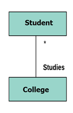
A multiplicity is a factor associated with an attribute. It specifies how many instances of attributes are created when a class is initialized. If a multiplicity is not specified, by default one is considered as a default multiplicity.
Let's say that that there are 100 students in one college. The college can have multiple students.
Aggregation
Aggregation is a special type of association that models a whole- part relationship between aggregate and its parts.

For example, the class college is made up of one or more student. In aggregation, the contained classes are never totally dependent on the lifecycle of the container. Here, the college class will remain even if the student is not available.
Composition:

The composition is a special type of aggregation which denotes strong ownership between two classes when one class is a part of another class.
For example, if college is composed of classes student. The college could contain many students, while each student belongs to only one college. So, if college is not functioning all the students also removed.
Aggregation vs. Composition
| Aggregation | Composition |
|---|---|
| Aggregation indicates a relationship where the child can exist separately from their parent class. Example: Automobile (Parent) and Car (Child). So, If you delete the Automobile, the child Car still exist. | Composition display relationship where the child will never exist independent of the parent. Example: House (parent) and Room (child). Rooms will never separate into a House. |
Abstract Classes
It is a class with an operation prototype, but not the implementation. It is also possible to have an abstract class with no operations declared inside of it. An abstract is useful for identifying the functionalities across the classes. Let us consider an example of an abstract class. Suppose we have an abstract class called as a motion with a method or an operation declared inside of it. The method declared inside the abstract class is called a move ().
This abstract class method can be used by any object such as a car, an animal, robot, etc. for changing the current position. It is efficient to use this abstract class method with an object because no implementation is provided for the given function. We can use it in any way for multiple objects.
In UML, the abstract class has the same notation as that of the class. The only difference between a class and an abstract class is that the class name is strictly written in an italic font.
An abstract class cannot be initialized or instantiated.

In the above abstract class notation, there is the only a single abstract method which can be used by multiple objects of classes.
Example of UML Class Diagram
Creating a class diagram is a straightforward process. It does not involve many technicalities. Here, is an example:
ATMs system is very simple as customers need to press some buttons to receive cash. However, there are multiple security layers that any ATM system needs to pass. This helps to prevent fraud and provide cash or need details to banking customers.
Below given is a UML Class Diagram example:

UML Class Diagram Example
Class Diagram in Software Development Lifecycle
Class diagrams can be used in various software development phases. It helps in modeling class diagrams in three different perspectives.
1. Conceptual perspective: Conceptual diagrams are describing things in the real world. You should draw a diagram that represents the concepts in the domain under study. These concepts related to class and it is always language-independent.
2. Specification perspective: Specification perspective describes software abstractions or components with specifications and interfaces. However, it does not give any commitment to specific implementation.
3. Implementation perspective: This type of class diagrams is used for implementations in a specific language or application. Implementation perspective, use for software implementation.
Best practices of Designing of the Class Diagram
Class diagrams are the most important UML diagrams used for software application development. There are many properties which should be considered while drawing a Class Diagram. They represent various aspects of a software application.
Here, are some points which should be kept in mind while drawing a class diagram:
- The name given to the class diagram must be meaningful. Moreover, It should describe the real aspect of the system.
- The relationship between each element needs to be identified in advance.
- The responsibility for every class needs to be identified.
- For every class, minimum number of properties should be specified. Therefore, unwanted properties can easily make the diagram complicated.
- User notes should be included whenever you need to define some aspect of the diagram. At the end of the drawing, it must be understandable for the software development team.
- Lastly, before creating the final version, the diagram needs to be drawn on plain paper. Moreover, It should be reworked until it is ready for final submission.
Conclusion
- UML is the standard language for specifying, designing, and visualizing the artifacts of software systems
- A class is a blueprint for an object
- A class diagram describes the types of objects in the system and the different kinds of relationships which exist among them
- It allows analysis and design of the static view of a software application
- Class diagrams are most important UML diagrams used for software application development
- Essential elements of UML class diagram are 1) Class 2) Attributes 3) Relationships
- Class Diagram provides an overview of how the application is structured before studying the actual code. It certainly reduces the maintenance time
- The class diagram is useful to map object-oriented programming languages like Java, C++, Ruby, Python, etc.
- Follow this curated list to create a professional diagram – Click here.
Source: https://www.guru99.com/uml-class-diagram.html
Posted by: nemunaitisluisaees.blogspot.com

Posting Komentar untuk "Uml Class Diagram Notation Pdf"